Honda Xr200 Wiring Diagram, Skygo150 Voltage Regulator for XR200/Actual Wiring/Honda XR200 Modified/Supermoto/DIY Garage PH, 10.03 MB, 07:18, 10,383, D I Y Garage PH, 2021-01-23T08:48:03.000000Z, 19, Iam looking for a 1982 honda xr200 wiring diagram, www.justanswer.com, 904 x 703, jpeg, wiring diagram 1982 honda xr200 xt200 yamaha manual iam motorcycle looking 1981 mechanic bikee wire, 20, honda-xr200-wiring-diagram, Anime Arts
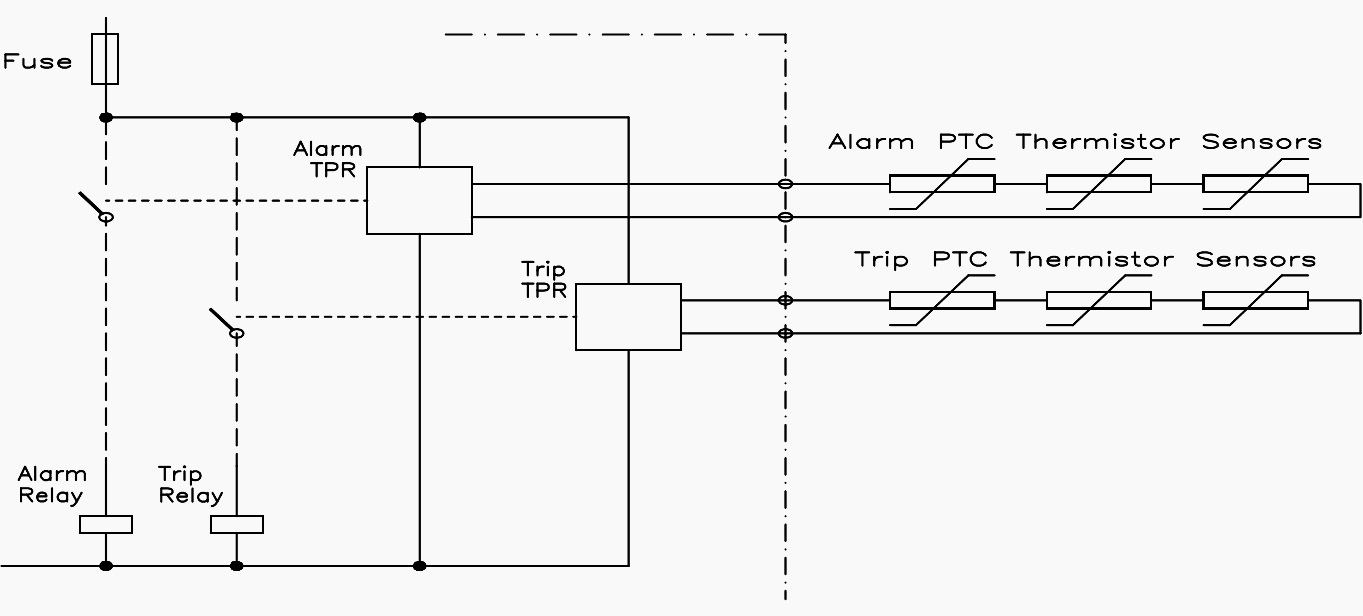
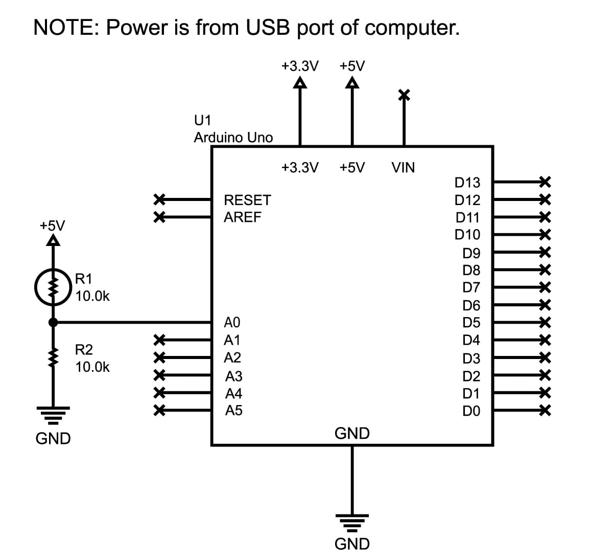
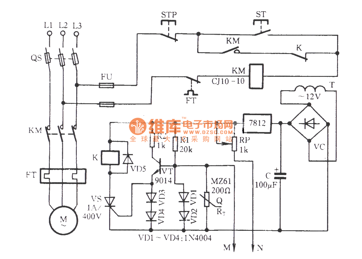
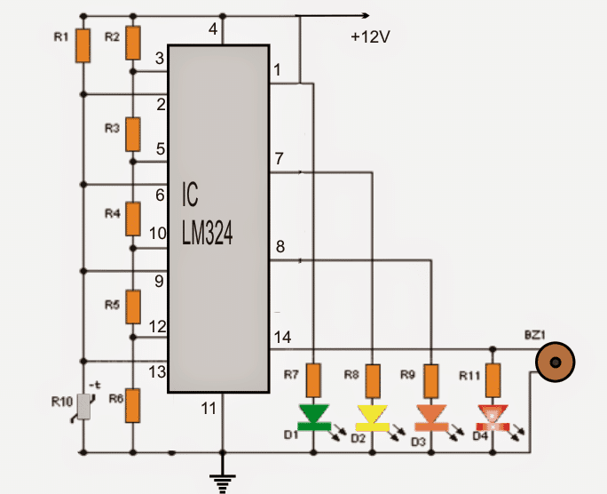
The devices are available with two different terminal versions. The wiring diagram of the ptc thermistor is shown below. This application circuit is used for protecting transistor circuits from overvoltage. In this transistor amplifier circuit, a ptc thermistor is used in an easy & convenient way to defend transistor circuits from an increase in an ambient temperature otherwise from heat generated through the transistor.
· ptc thermistor pellet with insulating encapsulation. ·low resistance type, steep r/t curve. ·fast response due to small dimensions. ·characteristics for sensing temperatures conform with din 44081 for 1 ptc single sensor, din 44082 for 3 ptc in series triplet sensors. Brake = 230v brake control: Motor configured for high voltage. Brake voltage matches the low motor voltage. 230v / 460v motor configured for 460v ( ) • brake voltage is 230v [1] motor terminal board [4] sr current relay [2] supply leads [5] terminal strip Each specific thermistor has its own unique resistance vs. temperature characteristic.
Motor Winding Thermistor Wiring Diagram - Wiring Diagram

Motor Thermistor Wiring Diagram - Wiring View and Schematics Diagram

Motor Winding Thermistor Wiring Diagram - Wiring Diagram

Reliance Motor Wiring Diagram Thermistor | Wiring Diagram - Baldor Motor Wiring Diagram | Wiring

43 Motor Thermistor Wiring Diagram - Wiring Diagram Source Online

39 3 Phase Motor Thermistor Wiring Diagram - Wiring Diagram Online Source

43 Motor Thermistor Wiring Diagram - Wiring Diagram Source Online

39 3 Phase Motor Thermistor Wiring Diagram - Wiring Diagram Online Source
39 3 Phase Motor Thermistor Wiring Diagram - Wiring Diagram Online Source

47 3 Phase Motor Thermistor Wiring Diagram - Wiring Diagram Source Online
